
Cpu Fan Black Yellow Green Blue
Cpu Fan Black Yellow Green Blue, Indeed recently has been hunted by consumers around us, perhaps one of you personally. People now are accustomed to using the internet in gadgets to view video and image information for inspiration, and according to the name of this article I will discuss about
If the posting of this site is beneficial to our suport by spreading article posts of this site to social media marketing accounts which you have such as for example Facebook, Instagram and others or can also bookmark this blog page.

4 Wire Pc Fan 971 The Fan Golf Outing 2019
Asus Rog Strix 1080 Ti Fan Connector Techpowerup Forums 971 The Fan Golf Outing 2019
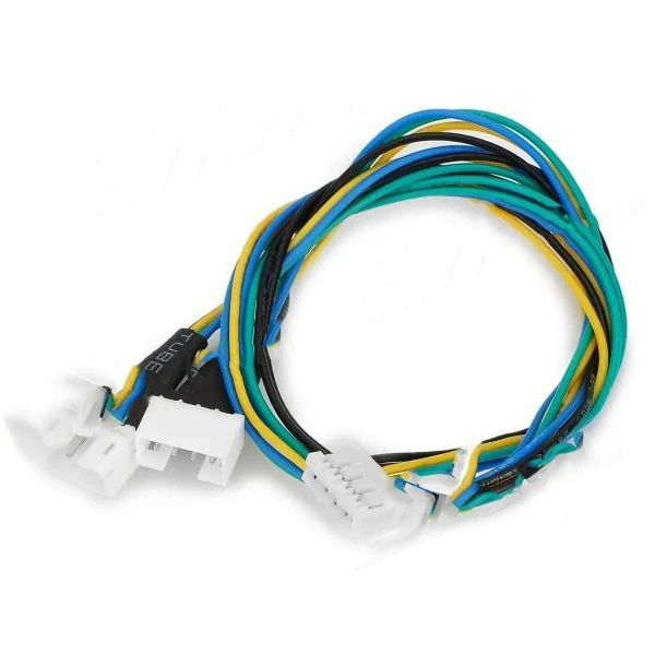
Cuddle 4 Pin Extension Power Splitter Cable For Pc For Dc Cooling Cpu Fan Black Yellow Green Blue Cable Splitter Price Cable Splitter Boxcable Convert Aliexpress 971 The Fan Golf Outing 2019
Pc Pinouts Easypconline 971 The Fan Golf Outing 2019

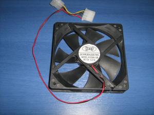
4 Wire Pc Fan 971 The Fan Golf Outing 2019
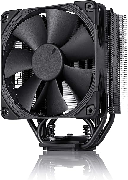
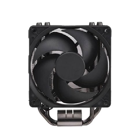
Amazon Com Noctua Nh U12s Chromax Black 120mm Single Tower Cpu Cooler Black Computers Accessories 971 The Fan Golf Outing 2019
Reduce the voltage by a pwm controller rheostat or potentiometer will reduce the speed later it evolved into the 3 pin standard.
971 the fan golf outing 2019. Simply connect yellow and red to 12v and the fan will run. This transistor is there to permit the monitoring of the motors speed. I had in hand fan nidec f09a 12b3s1 which is supplied with boxed intel.
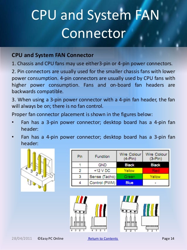
Fans and on board fan headers are backwards compatible. I think you will need to apply 48 volts to get the fan operating. Example of 4 wire fan.
Once it is operating i think you will find that the yellow and blue wires are the collector and the emitter of a sensor transistor. 4 pin connectors are usually used by cpu fans with higher power consumption. Few cpu fan standards.
Dunno if you found your answer or if too late but just saw this thread and this is what my pc case building buddy told me. Black yellow and the third lead. As others have mentioned i believe you have a 48v fan.
The third is to report fan speed and can be ignored. Two pin black and yellow full speed is 12v. 3 pin connectors are usually used for the smaller chassis fans with lower power consumption.
Diode d1 protects pwm output from motherboard in case that fan has pull up to 5v and motherboard logic is on 33v. Black is ground red is 12volt power yellow will be the speed senserpm tachometer and blue is for pwm function which allows the mb to automatically control the fan speedby voltage for temperature.
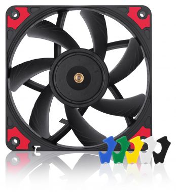
Nf A12x15 Pwm Chromax Black Swap 971 The Fan Golf Outing 2019
Fans Heatsinks Cooling Cpu Fans Computer Cooling Best Buy 971 The Fan Golf Outing 2019

Rgb Led Fan System Cooling Products X2 Products 971 The Fan Golf Outing 2019

Proprietary Fan Header Issues Dell Community 971 The Fan Golf Outing 2019