
Fan Controller Circuit
Fan Controller Circuit, Indeed recently has been hunted by consumers around us, perhaps one of you personally. People now are accustomed to using the internet in gadgets to view video and image information for inspiration, and according to the name of this article I will discuss about
If the posting of this site is beneficial to our suport by spreading article posts of this site to social media marketing accounts which you have such as for example Facebook, Instagram and others or can also bookmark this blog page.
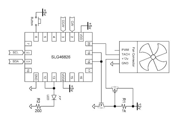
Build A Pwm Controller For Pc Fans With Greenpak Industry Articles Box Fan Uae
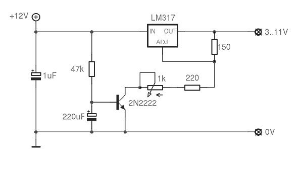
Lm317 Fan Speed Controller Circuitlab Box Fan Uae
1 Box Fan Uae
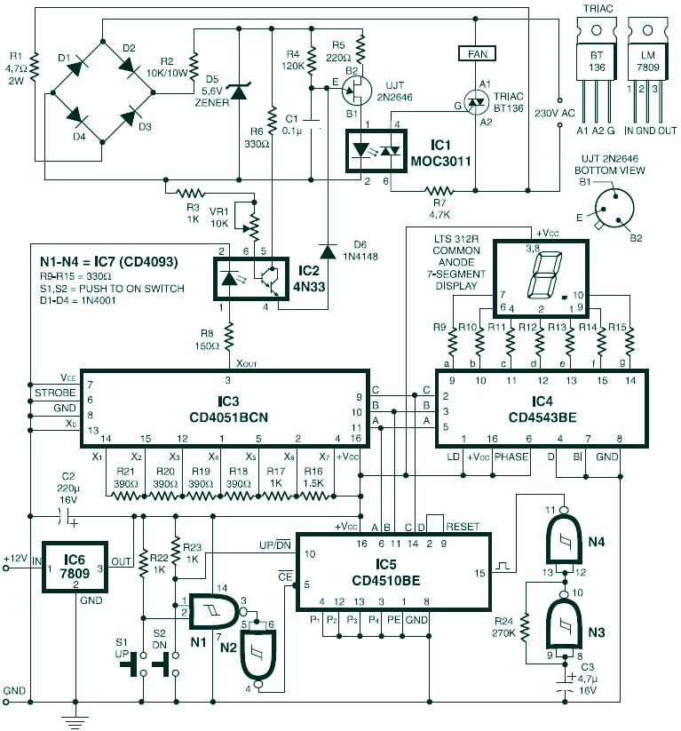
Digital Fan Speed Control Electronic Schematic Diagram Box Fan Uae

Pc Fan Speed Controller For A Low Noise Pc Electronic Circuits Box Fan Uae

Intelligent Pc Fan Controller Handson Tech Box Fan Uae
The latest circuit post was a set of some circuits so easy that even a kid can do.
Box fan uae. The modulation is a process of varying the parameter of a carrier signal in accordance with the instantaneous value of the message signal. The system cables this fan controller is equipped with are aimed at maximum control over the temperature and speed of the pc. This cable system delivers clean and accurate voltage as it is powered directly by sat cable from the pc power supply.
Until now i have present several pwm circuits to control a fan yet these are rather difficult for a simple pc moder to implement. In that case a lot of the newer motherboards use pwm to control their fan circuits especially the higher end ones. Breadboard and connecting wires circuit diagram.
Pwm signal generation circuit. Phase angle controlling circuit 3. It allows expanding a motherboard pwm fan header to support eight fans.
The ac supply we get in our household is 220v ac rms 50 hz. Ceiling fan speed control wiring diagram first of all i want to clear you that we can control the fan motor speed using 3 method in which we can do the ceiling fan motor speed control using two methods while in stand fan motor we can also regulate the speed by doing the connections in axillary winding starting winding. They are as follows.
A pc fan along with a heat sink is an excellent active cooling system for computers. The working can be divided into four different parts. Dc fan speed regulator circuit dc fan motor speed controller regulator circuit works on principle of pulse width modulation pwm technique by using this technique controlling of dc motor speed is very smoothly and noise free.
Pwm fan controller circuitdb pwm motor controller for dc motors and fans intelligent pc fan controller handson tech details about 12v pwm pc cpu fan temperature control sd controller module high temp alarm pwm fan circuit reading wiring diagrams. By saum hadi posted on november 6 2018. Most modern motherboards include a provision for on board cpu fan control.
Below is the circuit diagram for temperature controlled dc fan using thermistor as temperature sensor. Potentiometer to control the fan speed amount 4. Working of pc fan controller circuit.
Working of ac fan control using arduino. In continue to an older set of circuits simple ways to make fans silent i decided to fulfill the fan controller circuits. This is where this controller comes in.
Note the crude circuit diagram on the black box object the fan speed controller i infer that the fan controller works by inserting a capacitance into the fans power supply circuit. This heat must be removed efficiently and quietly. The key component of this temperature controlled fan circuit is thermistor which has been used to detect the rise in temperature.
In a normal pc or notebook pc most of the heat generated is by the processor. Pwm pc fan controller circuit. The slow speed is obtained by using the 43uf capacitor purple p the medium speed is obtained by using the 21uf capacitor red r and the high speed is.
Efficient Muffin Fan Speed Controller Atm Optics And Diy Forum Cloudy Nights Box Fan Uae

Automatic Dc Fan Controller Using Thermister For Cpu And Amplifier Box Fan Uae

Why And How To Control Fan Speed For Cooling Electronic Equipment Analog Devices Box Fan Uae
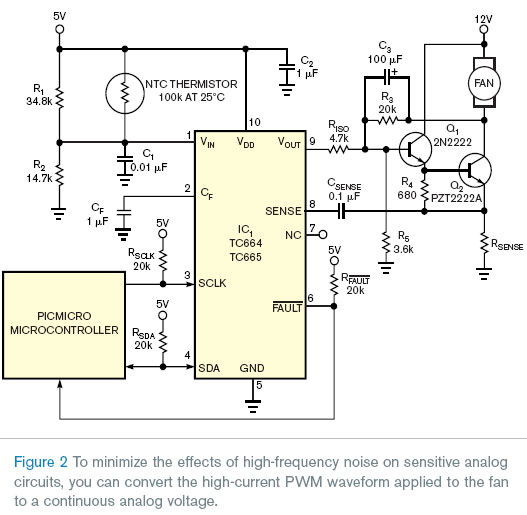
Use A Pwm Fan Controller In An Emi Susceptible Circuit Box Fan Uae